
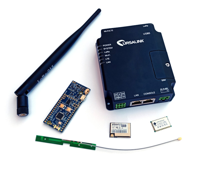
This post demonstrates how to connect a Talk2 Whisper Node to The Things Network (TTN) via an Ursalink UG85 multi-channel gateway.
The Talk2 Whisper Node is a small LoRa enabled microcontroller board which can be used to send data to an application via the TTN. For the data to get to TTN, it requires a LoRaWAN gateway, which in this project, we are using the mighty Ursalink UG85.
This project is rather simple, and for someone who has some experience with microcontrollers and different device connection, it should take around 3 to 4 hours for a first attempt.
Apart from the hardware elements, this project also relies on a few libraries worth mentioning. It uses TinyLoRa by Adafruit, and the Wisen developed Talk2 library. For LoRa only messages the Radiohead library, developed by Mike McCauley, can be utilised.
[Diagram]
Gateway
We've chosen the Ursalink UG85 for this project because of its extreme versatility and ease of use. The Gateway has been configured to connect with the Internet via a 4G link, which supports up to two SIM Cards with fail-over capabilities.
The LoRaWAN configuration is straightforward and can even be done remotely, using the Ursalink DeviceHub. In this experiment the only configuration required is for the LoRa radio to operate in the AU915 band as well to have the Gateway provisioned in the TTN.
If you are inside an area covered by any other LoRaWAN gateway connected to the TTN, you can skip this step. Otherwise, if you wish to deploy your own gateway check this video tutorial to see how simple it is: https://www.youtube.com/watch?v=OklDvim2uKw
If you're serious about IoT, make sure you choose an appropriated gateway. Alternative solutions based on a single-channel device or modular hardware are acceptable for testing or small deployment but should be avoided in real projects.
First Step: Configuring the IDE
The first step is to get the Whisper Node Talk2 working correctly in the Arduino IDE. This requires the configuration for the Talk2 Boards in the Arduino software. This is an important step because it facilitates the IDE to compile and upload projects to the Whisper Node.
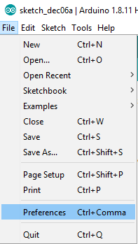
To add the board configuration, open the Preferences from the File menu.
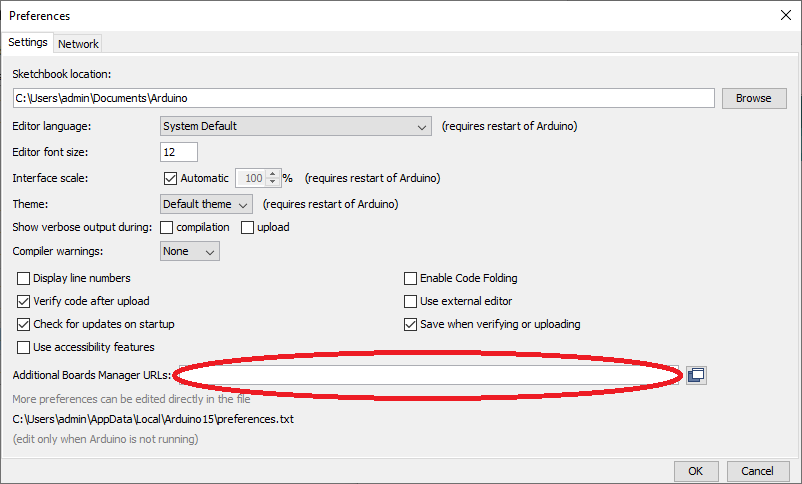
From the Preferences tab, find the text box titled “Additional Boards Manager URLs”, highlighted in the next image in red.
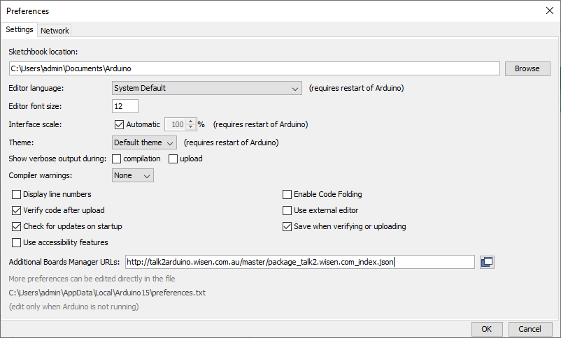
Once this window is open, you must put the following link to an online board configuration inside the text box: https://bitbucket.org/talk2/arduino-ide-boards/raw/master/package_talk2.wisen.com_index.json. It should look like the following:
If necessary, multiple URLs can be added separated by comma.
Once the URL is included in the preferences, the board configuration needs to be installed. To perform this step, open the board manager by opening the Tools menu, then Board, then Board Manager, as shown in the image below.
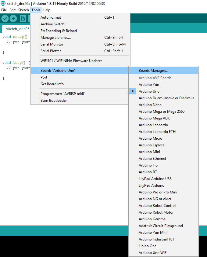
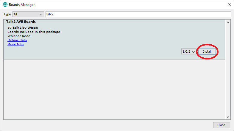
Now, in the Board Manager, you should now be able to search for “talk2”, which will then bring up the following display. To install the configuration for the board, simply click install, as circled in red.
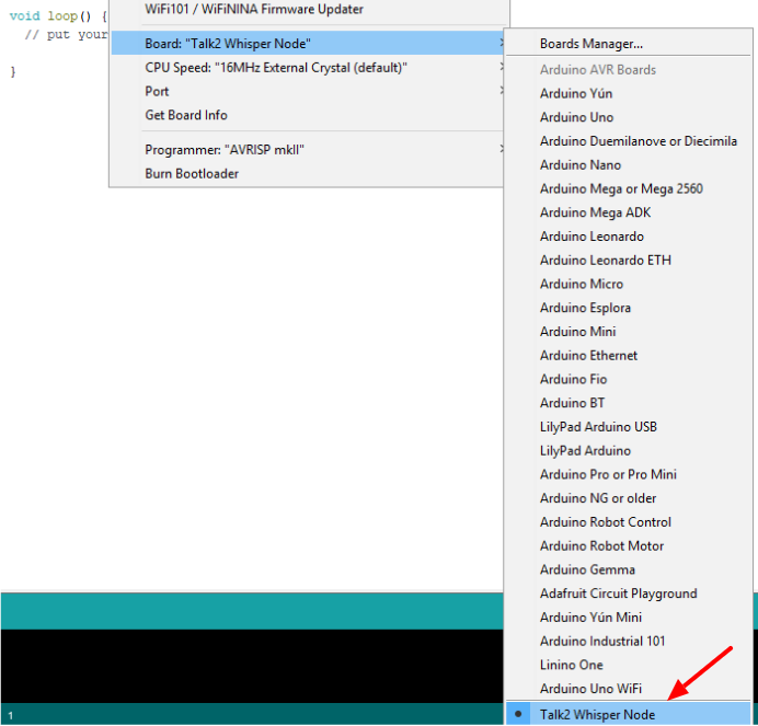
If the process has been followed correctly up to this point, you should now be able to select "Talk2" as a board from the Tools->Boards menu. Whenever you are attempting to program the Whisper Node, this board must be selected.
Step 2: Installing the required libraries
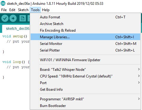
To install the first library, open up the Manage Libraries from the Tools menu as demonstrated below:
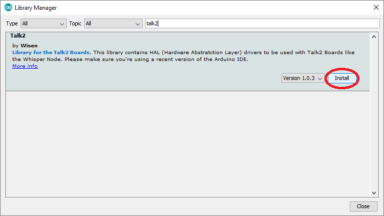
Inside the Manage Libraries screen, you can then search for the “talk2” library then install it by clicking the install button circled in red.
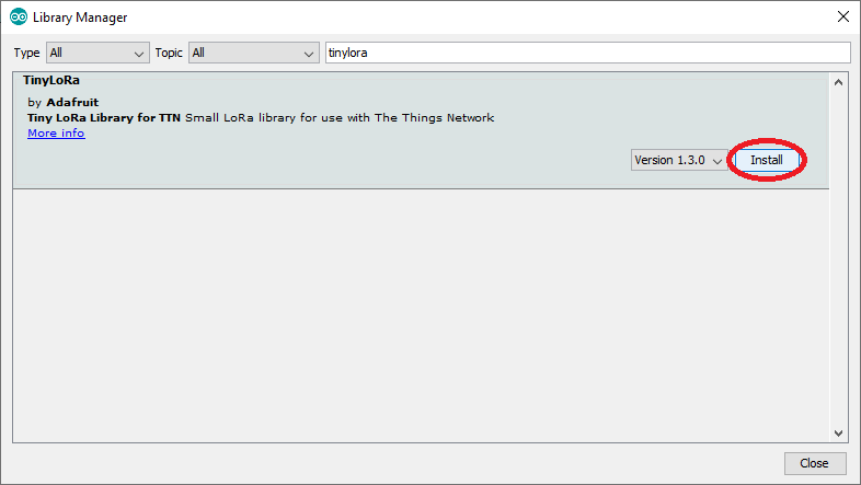
While you have the library manager open, also search for the "tinyLoRa" library created by Adafruit and install it by clicking the circled install button as shown below.
A third library, Radiohead, can also be installed however it cannot be opened from the Manage Libraries windows within the Arduino IDE. Instead, the library must be downloaded as a .zip file from the author website: http://www.airspayce.com/mikem/arduino/RadioHead/. At the time this article was written, the latest version available was http://www.airspayce.com/mikem/arduino/RadioHead/RadioHead-1.97.zip
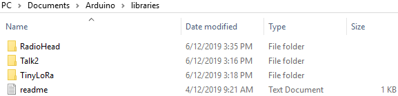
Once the file is downloaded, it's necessary to extract it using a zip extraction software. Find the Arduino libraries folder, by default under "Documents", then select the libraries folder and extract it inside the libraries folder. The folders for both the "Talk2" and the "TinyLoRa" libraries should both already be there. The picture below displays an example of what it should look like.
Once this last step is complete, restart the Arduino IDE and verify the libraries available.
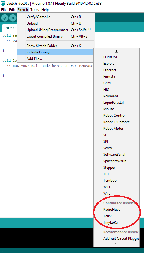
Inside the menu Sketch -> Include Libraries, the 3 libraries should show up under the “contributed Libraries” section as per the picture below, the relevant libraries are highlighted by being circled in red.
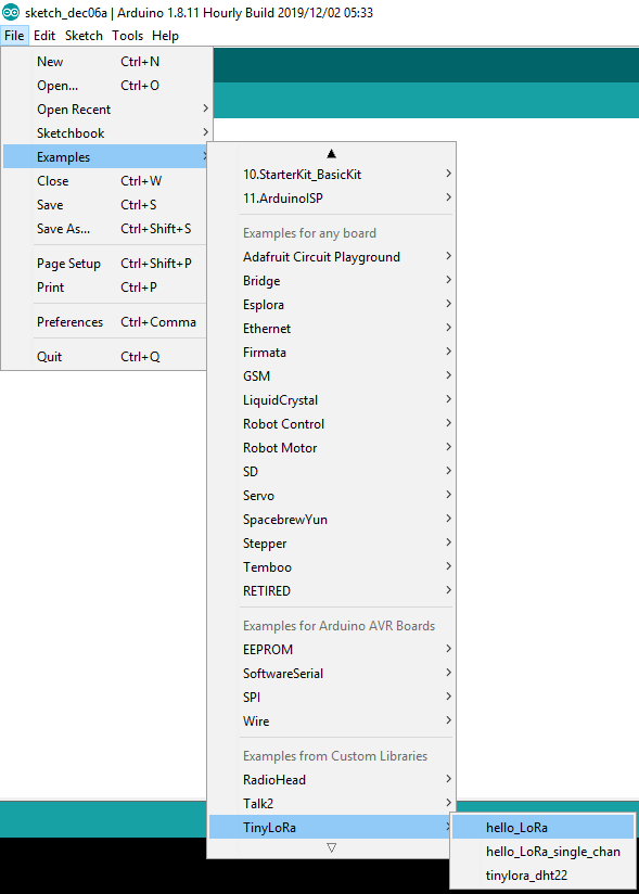
Step 3: Creating a Sketch
For the purposes of this blog, we will be using a program which has already been written called “hello_LoRa”. It's included in the “TinyLoRa” library and can be accessed by opening the File menu, selecting the Examples option, selecting “TinyLoRa” and finally “hello_LoRa”. Refer to the image below.
A few changes need to be made to the source code because it was originally written for a different microprocessor.
The first change is related to the pinout for the Whisper Node. Note that the original Pinout is commented out and a new one has been added:
// How many times data transfer should occur, in seconds
const unsigned int sendInterval = 30;
// Pinout for Adafruit Feather 32u4 LoRa
//TinyLoRa lora = TinyLoRa(7, 8, 4);
// Pinout for Adafruit Feather M0 LoRa
//TinyLoRa lora = TinyLoRa(3, 8, 4);
// Pinout for Whisper Node LoRa
TinyLoRa lora = TinyLoRa(2, 10, 7);
The only other change which needs making at this point is the changing of the words “LED_BUILTIN” with the number “9”. This needs to be done in three places, as demonstrated below.
// Initialize pin LED_BUILTIN as an output
pinMode(9, OUTPUT);
and
// blink LED to indicate packet sent
digitalWrite(9, HIGH);
delay(1000);
digitalWrite(9, LOW);
Because we're using the AU915 channel band, a second file has to be changed: “ TinyLoRa.h”. This file can be found within the TinyLoRa folder within the Libraries folder in the Arduino folder, for example: Documents\Arduino\libraries\tinyLoRa\tinyLoRa.h
Open the file in any text editor, perform the changes as described below and save it.
/** Region configuration*/
#define AU915 ///< Used in Australia
#if !defined(EU863) && !defined(AU915) && !defined(AS920)
#define US902 ///< Used in USA, Canada and South America
#endif
//#define EU863 ///< Used in Europe
//#define AU915 ///< Used in Australia
//#define AS920 ///< Used in Asia
As you can see, just add the #define AU915 before the #if statement. Depending on your region or gateways configuration this might be different.
At this point you should be able to try to compile and upload the firmware to the board. Open the "Serial Monitor" and observe the LED blinking on every transmission.
Final Step: TTN and Device Configuration
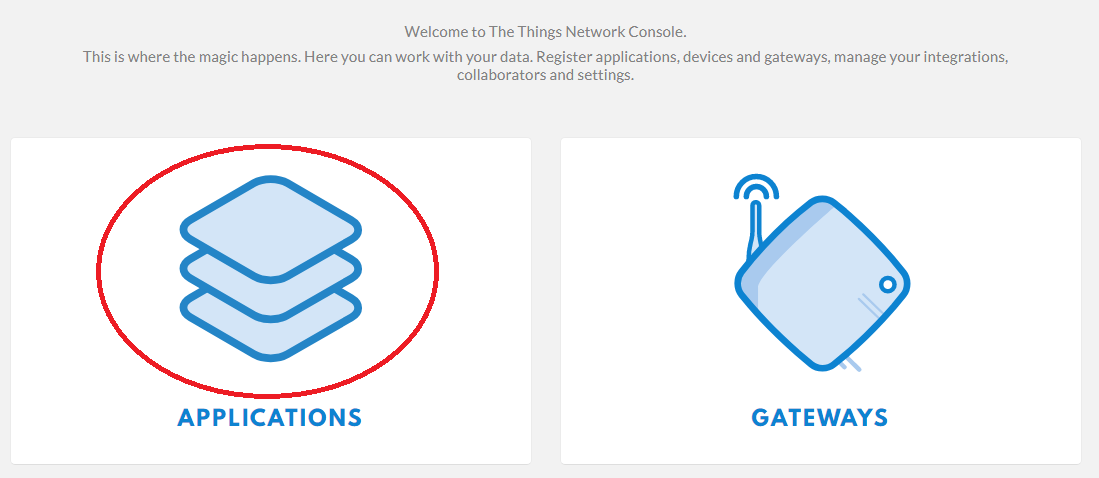
To create an application on TTN, you go to the TTN website at https://www.thethingsnetwork.org/ then either create an account or sign in.
After you have authenticated, navigate on the site to your console directly via link: https://console.thethingsnetwork.org/
On the console, click the button labelled as “Applications” then select it. Below is an example of what you should see and the correct button to press is highlighted in red.
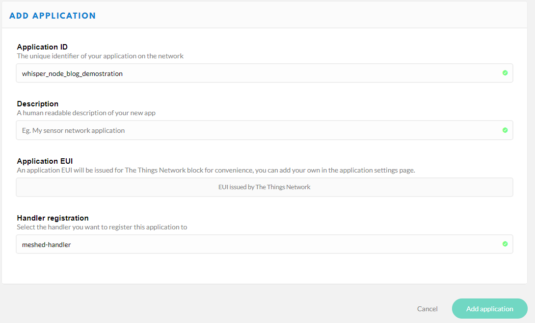
From there, you should see the following header with the "add application" button, click on it

Then you create an application by filling out an application creation form. An example of how to do this is in the following images.
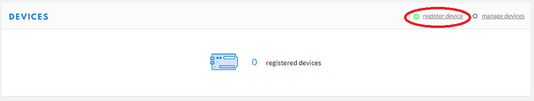
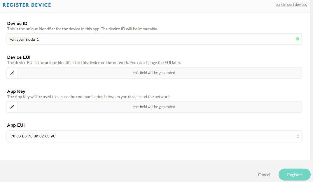
Once the application is created, you will be brought to a page with a devices section which contains a button labelled "register device". Click this button as per image below.
You will then be brought to another form for the device. An example of how to fill in the form is provided in the image below.
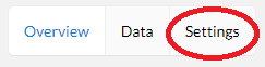
Once a device is registered, you will then be taken to the device’s page and you will see a three button menu with the buttons “Overview”, “Data” and “Settings”. Select the Settings button. An example of the button to press is circled in red in the following image.
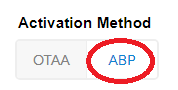
You need to find the setting labelled “activation mode” and change the mode so that it is ABP not OTAA.
Once you have saved the change, you will be brought back to the overview page and you will see some information labelled as “Device Address”, “Network Session Key” and “App Session Key”.
Expand the information to an human understandable form by pressing the buttons circled in red below. Then press the button which is circled blue to copy the information to the clipboard. The information needs to be pasted into the “hello_LoRa” file and replace the variables in the code which are currently simply placeholders which are just all 0x00.
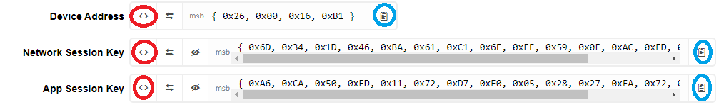
Replace the variables so that they match the respective variables found on your device for your particular TTN application.
An example of what this might look like follows below:
// Network Session Key (MSB)
uint8_t NwkSkey[16] = { 0x6D, 0x34, 0x1D, 0x46, 0xBA, 0x61, 0xC1, 0x6E, 0xEE, 0x59, 0x0F, 0xAC, 0xFD, 0x8A, 0xF6, 0x2F };
// Application Session Key (MSB)
uint8_t AppSkey[16] = { 0xA6, 0xCA, 0x50, 0xED, 0x11, 0x72, 0xD7, 0xF0, 0x05, 0x28, 0x27, 0xFA, 0x72, 0x9D, 0xD3, 0x00 };
// Device Address (MSB)
uint8_t DevAddr[4] = { 0x26, 0x00, 0x16, 0xB1 };
While you are still in the settings for the device, you want to disable the “Frame Counter Checks” option as per image below:

The "Frame Counter Checks" is used by the LoRaWAN server to ignore any message with repeated frame counter. This is used to prevent replay attacks but will require the node or device to keep track of this sequence. For this simple example, every time the device gets restarted the counter is reset to zero.
If you would like to verify the transmission of data to your application, you can click the data tab and the message should appear as well as some information about the data transmission. It should look similar to the following:
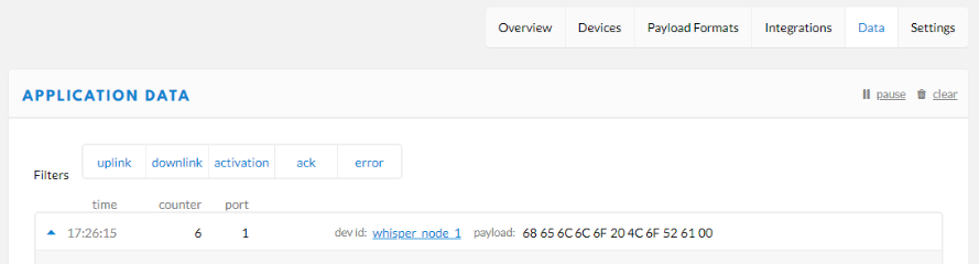
The message content will be in binary format.
Conclusion
This project is a basic demonstration for a “hello world” style program. It shows the basics steps to set up a board with LoRaWAN capabilities and to connect it to TTN.
A very similar project could be conducted to perform tasks such as transmitting data from a sensor attached to the Whisper Node board. This project is designed to get the basics of LoRa connection to TTN operating, any functionality for a sensor for example would require additional programming of the Whisper Node.